Menu
Your cart is empty
Looks like you haven't added anything to your cart yet

Dresser Pipeline Cap
Availability
Type
Price
$0
$5,563.21
Dresser Style 31 Line Cap - Steel Pipe, 2 in to 24 in

Dresser
Dresser Style 31 Line Cap - Steel Pipe, 2 in to 24 in
- Price
- From $368.48
Dresser Style 31 Line Cap - Cast Iron Pipe, 2 in to 24 in
Dresser
Dresser Style 31 Line Cap - Cast Iron Pipe, 2 in to 24 in
- Price
- From $476.48
Dresser Pipeline Cap
Description
Dresser Style 31 Line Caps
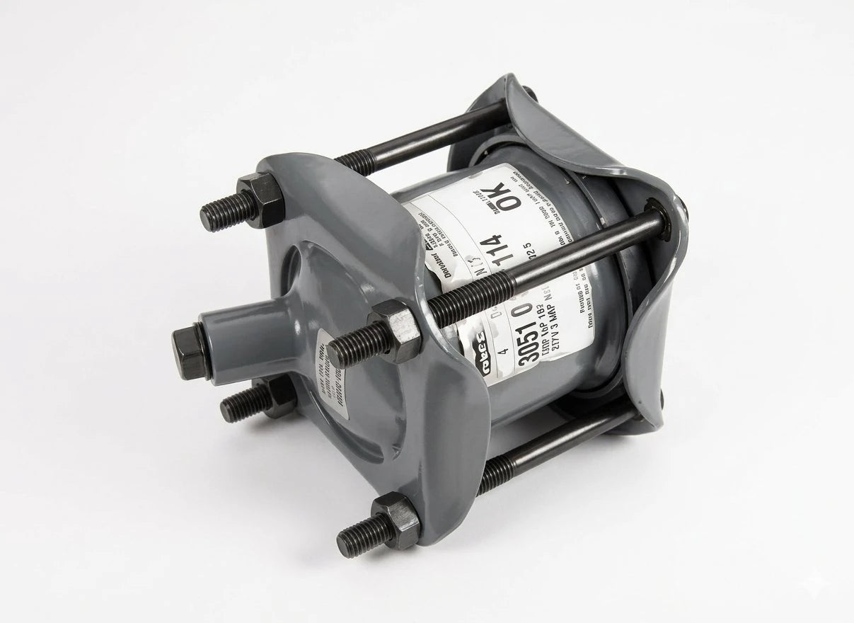
The Dresser Style 31 Line Cap provides a permanent or temporary mechanical seal at an open pipe end — no welding, no threading, no flanging. Available for both steel IPS pipe and cast iron pipe ODs, from 2" through 12" and beyond.
31
Style Number
2"–12"+
Size Coverage
Permanent or Temp
Installation Type
Product Lines
Steel Pipe & Cast Iron Pipe Versions
The Style 31 body is identical in function across both series — the only difference is the OD bore dimension machined to fit the respective pipe standard.
31Steel IPS
Style 31 — Steel Pipe Line Cap
Sized to IPS outer diameter dimensions. Single follower ring compresses an elastomeric gasket against the pipe OD to create a pressure-rated mechanical seal at any open pipe end. No modification to pipe required.
31Cast Iron
Style 31 — Cast Iron Pipe Line Cap
Machined to cast iron OD dimensions. Seals abandoned CI mains, dead-end branches, and blow-off points without requiring the pipe to be drained or dewatered prior to cap installation.
Where Line Caps Are Used
Five Scenarios That Drive Line Cap Orders
Line caps are not a high-volume commodity — but when you need one, there is no substitute.
01
Main Abandonment
When a distribution main is taken out of service but not physically removed, Style 31 caps both ends. Avoids costly excavation for flange plate welding.
02
Dead-End Blow-Offs
Temporary cap during system construction allows pressure testing of completed pipe segments before blow-off valves are installed.
03
Stub-Out Sealing
Service stubs left from main extensions are capped with Style 31 until a customer connection is made — sometimes years later.
04
Hydrostatic Testing
Cap both ends of a new main segment, connect a pump, and pressure test to 1.5× working pressure before tie-in to the live system.
Critical Specification Point
Steel OD vs Cast Iron OD — Do Not Confuse
Ordering a steel-OD cap for cast iron pipe — or vice versa — results in a cap that either won't slide on, or won't seal. Verify pipe OD before ordering.
| Nominal | Steel IPS OD | Cast Iron OD | Correct Cap |
|---|---|---|---|
| 2" | 2.375" | 2.500" | Specify pipe material |
| 3" | 3.500" | 3.960" | Specify pipe material |
| 4" | 4.500" | 4.800" | Specify pipe material |
| 6" | 6.625" | 6.900" | Specify pipe material |
| 8" | 8.625" | 9.050" | Specify pipe material |
| 12" | 12.750" | 13.200" | Specify pipe material |
Field Verification Method
Wrap a cloth tape measure around the pipe and divide the circumference by π (3.1416) to get the OD. Compare to the table above — within 0.1" of which standard tells you the pipe material class for cap selection.
PVC C900 Reminder
PVC C900 pressure pipe uses cast iron OD dimensions. If capping a C900 stub, order the cast iron OD version of the Style 31 cap.
Installation Procedure
Mechanical Cap Installation in Four Steps
No special tooling required. A torque wrench and a wire brush are the primary tools.
1
Clean the Pipe End
Wire brush 6–8" of pipe OD from the end. Remove all scale, rust, coating buildup, and burrs. The gasket must seat on a clean, reasonably smooth OD surface.
2
Slide Cap onto Pipe
Slide the Style 31 cap body and gasket over the pipe end. Center the gasket over the pipe end so it will compress uniformly when the follower is tightened.
3
Tighten Bolts in Pattern
Tighten bolts alternately in a cross pattern, in three stages. Do not fully torque one bolt before moving to the next. Final torque per Dresser torque table for that pipe size.
Engineering Note
Using Line Caps for Hydrostatic Testing
The Style 31 is rated to the same working pressure as the equivalent Dresser coupling for that pipe size. For testing, verify the cap WP exceeds 1.5× the intended test pressure before proceeding.
Thrust Restraint During Testing
An unrestrained line cap under hydrostatic test pressure is a projectile hazard. Install thrust blocks at both test caps and at any bend within the test segment before applying pressure. Do not rely on soil friction alone on short test sections.
Temporary vs Permanent
Style 31 line caps are approved for both temporary test caps and permanent abandonment seals. For permanent abandonment, add a bituminous or coal-tar wrap over the installed cap to protect against external corrosion on the exposed steel body.
Test Pressure: Max 1.5× WP Hold Time: Per AWWA C600 Restrain Before: Pressurizing Permanent Seal: Add external wrap Reuse: Inspect gasket before reuse
Ready to Order or Need Technical Help?
Contact our team for availability, custom sizing, and volume pricing on Dresser Utility Solutions products.
Email sales@watermainsupply.com Call 281.664.8000
- Choosing a selection results in a full page refresh.